


HYDAC automatic back-flushing filters
HYDAC AutoFilt® automatic filters remove solid particles from industrial and circulating water, emulsions, coolants, fuels and other process fluids. The filter elements clean themselves by back-flushing — no manual cleaning and no disposable elements to replace. Eight series are presented below: from compact filters for machine tools to filters handling thousands of cubic metres per hour, a hydropneumatic filter for fuels and oils, and the ATF hybrid strainer.
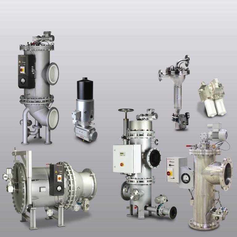
How automatic filters work
The fluid flows through stainless steel filter elements, and particles are retained on their surface. As contamination builds up, the differential pressure between the dirty and clean sides of the filter rises. When it reaches the set value — or on a timer, or on operator command — the control system starts back-flushing: the elements are connected to the back-flush line one after another, and a small amount of fluid flows through them in the reverse direction, carrying the contamination to the drain. The filter then returns to normal operation.
Only some of the elements are flushed at a time while the rest keep filtering the operating fluid, so in most filter versions the supply of filtered fluid is not interrupted during back-flushing (depending on the series and back-flushing mode).
- 1Filtrationparticles are retained on the filter elements
- 2Contamination builds updifferential pressure Δp rises
- 3Back-flushing startsby Δp, timer or manually
- 4Contamination removedthe reverse flow carries it to the drain
- 5Back to filtrationfull filtration capacity
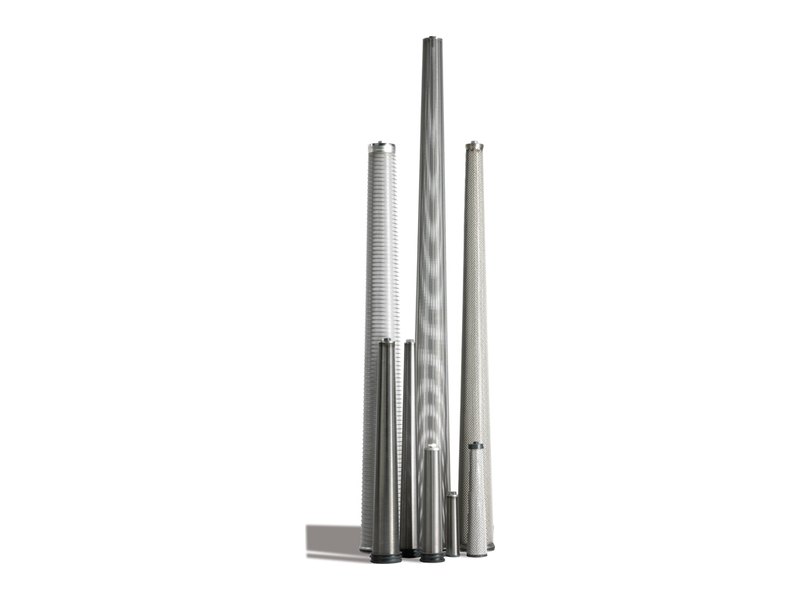
The series differ in how they clean
- Isokinetics
- RF3/RF6, RF5, RF7, RF4 — flushing with filtrate driven by the pressure difference between the clean side and the back-flush line
- JetFlush
- RF10, RF12 — hydrodynamic suction effect; back-flushing depends only on the inlet pressure
- Hydropneumatics
- RF9 — a piston impulse from compressed air, with no mixing of air and filtrate
- Hybrid
- ATF — centrifugal separation in a cyclone-type housing plus a conical wedge wire element, no rotating parts
HYDAC automatic filter range
Flow rates are given as the maximum for the series size range. For a specific size, the flow rate depends on the filtration rating, viscosity and contamination of the medium.
-
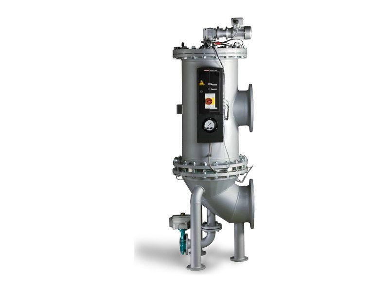
RF3/RF6
The main range for water and low-viscosity fluids: DN 50 to DN 900, up to 7,500 m³/h.
Conical elements, isokinetic back-flushing
More about the series -
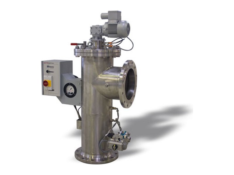
RF5
Vertical-inlet version for large pipelines: DN 250–900, up to 4,200 m³/h.
Vertical inlet, 200–3,000 µm
More about the series -
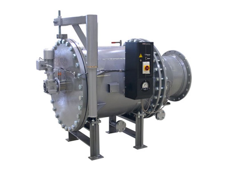
RF7
Horizontal housing for locations with limited height: up to 7,500 m³/h, 25–3,000 µm.
Low installation height, pivoting lid
More about the series -
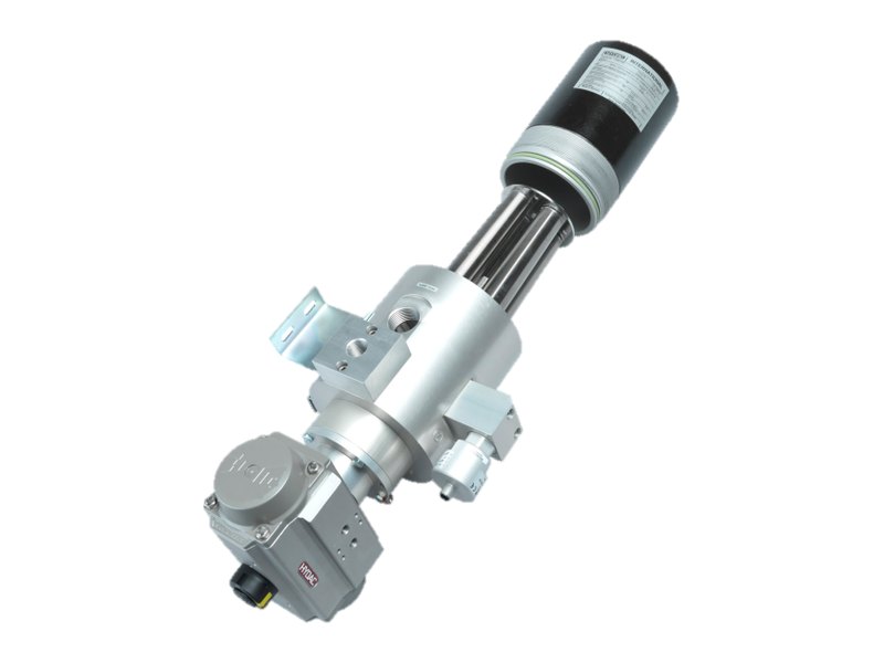
RF4
Compact filter for low flow rates — up to 385 l/min, threaded connections G 1"–G 2".
Coolants, water, washing fluids
More about the series -
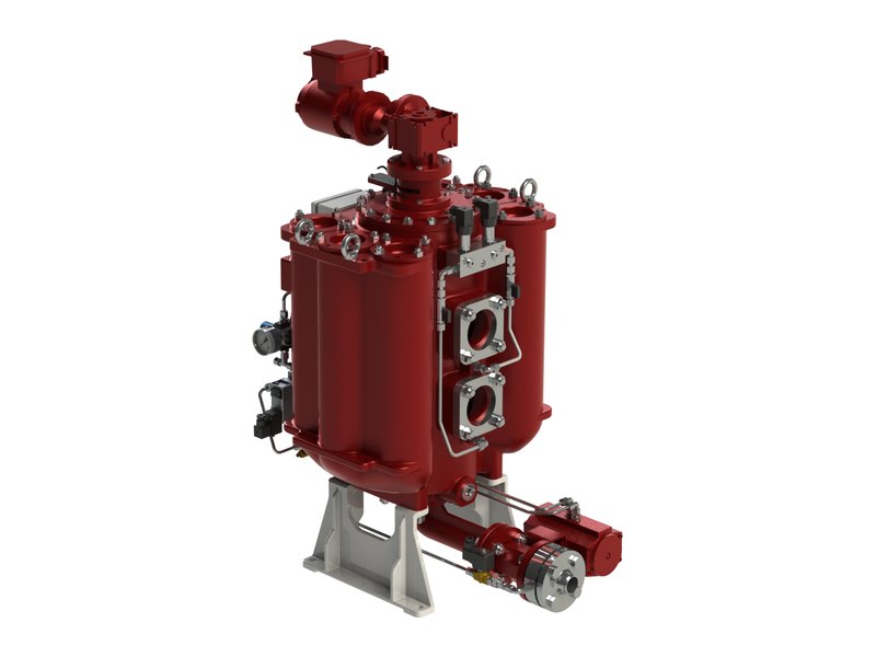
RF9
Heavy fuel oil and diesel, lubricating oils, coolants. Filtration from 1 µm, up to 180 °C.
Hydropneumatic back-flushing
More about the series -
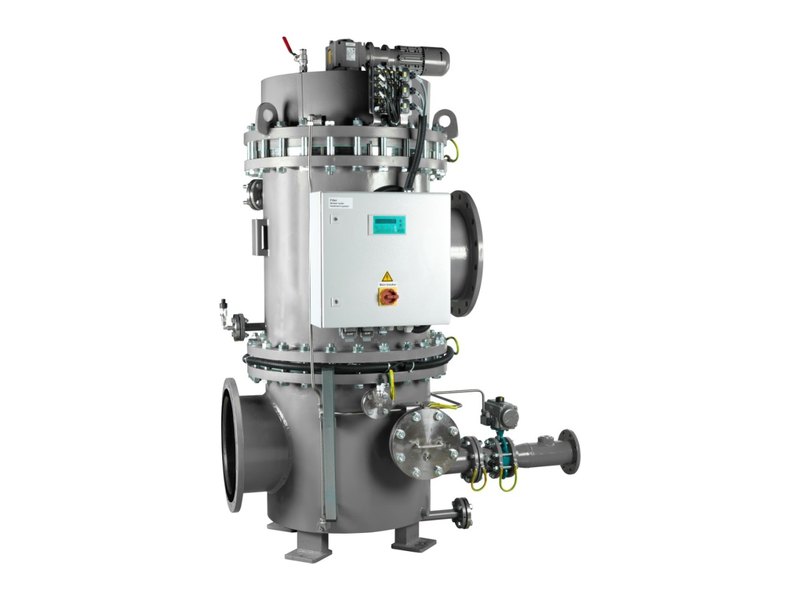
RF10
Ballast water and other systems with low pressure and long back-flush lines.
JetFlush: back-flushing depends only on the inlet pressure
More about the series -
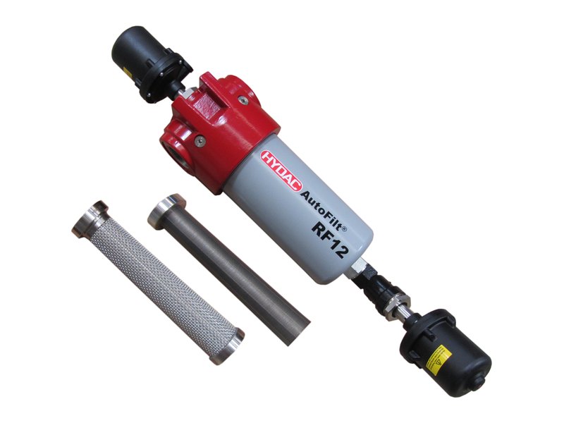
RF12
Compact filter for machine tools: up to 80 l/min, 25–100 µm, inlet pressure from 0.7 bar.
JetFlush, low-pressure coolant
More about the series -
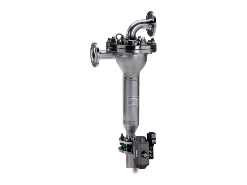
ATF
Hybrid strainer for water with high and fluctuating contamination — up to several grams per litre.
Centrifugal separation + wedge wire element
More about the series
Series in detail
RF3/RF6 — automatic back-flushing filters
up to 7,500 m³/h · 25–3,000 µm · water and low-viscosity fluids
RF3/RF6 is HYDAC's basic and most versatile automatic filter series. It separates solid particles from water and low-viscosity fluids and suits both new installations and the replacement of filters in existing ones: the flange positions are chosen to match the pipework. The filter is supplied ready to operate — once the pipes are connected, only the power supply is needed.
Operating principle and design
The fluid flows through conical wedge wire or mesh elements from the inside to the outside. During back-flushing, a gear motor moves the flushing arm under a contaminated element, the back-flush valve opens, and the pressure difference between the filtrate side and the back-flush line drives a small amount of filtrate back through the element. The elements are cleaned one after another while the others keep filtering. With cyclic control, the rapid opening of the pneumatic valve creates a pressure pulse that improves cleaning and reduces the back-flush volume.
Advantages
- Filtration is not interrupted during back-flushing.
- Conical elements: lower pressure drop, fewer back-flush cycles, less fluid lost to back-flushing.
- Variable flange positions make installation in an existing pipeline easier.
- ACU control unit with touchscreen, remote monitoring and Ethernet, RS-232/RS-485 interfaces.
Applications
Key specifications of RF3/RF6
| Connection | DN 50 – DN 900 |
|---|---|
| Flow rate | up to 7,500 m³/h (range maximum) |
| Filtration rating | 25–3,000 µm |
| Operating pressure | min. 2 bar; max. up to 100 bar depending on the version |
| Temperature | up to 90 °C |
| Filter elements | Chemicron® wedge wire; Chemicron® SuperMesh sintered wire mesh; optional SuperFlush non-stick coating |
| Housing | carbon or stainless steel; epoxy or polyurethane coating, or rubber lining |
| Back-flush control | electro-pneumatic or electrical, pneumatic, manual, via customer PLC |
RF5 — filter with vertical inlet
up to 4,200 m³/h · 200–3,000 µm · DN 250–900
RF5 uses the same technology as RF3/RF6 but is designed for high flow rates in a compact design and has a vertical inlet. The series is intended for large pipelines — DN 250 to DN 900 — and relatively coarse filtration of 200–3,000 µm: protecting heat exchangers, nozzles and equipment on cooling and service water lines.
Operating principle and design
The inlet is vertical, on the housing axis, and the outlet is at the side. This gives a different pipework layout from RF3/RF6 and is convenient when the pipeline reaches the filter from below. Inside are conical wedge wire elements with isokinetic back-flushing. In time-controlled versions the back-flush valve opens and the gear motor rotates the flushing arm continuously under the elements until the set time has elapsed. The filtrate flow is not interrupted.
Advantages
- High flow rates in a compact design.
- Vertical inlet — a layout alternative to RF3/RF6.
- Fully automatic operation, supplied as a ready-to-connect unit.
- Optimised pressure drop thanks to conical elements.
Applications
Key specifications of RF5
| Connection | DN 250 – DN 900 |
|---|---|
| Flow rate | up to 4,200 m³/h (range maximum) |
| Filtration rating | 200–3,000 µm |
| Operating pressure | 2–10 bar |
| Temperature | up to 90 °C |
| Housing | carbon or stainless steel; epoxy or polyurethane coating, rubber lining |
| Back-flush control | time control (electro-pneumatic, electrical), cyclic control (electro-pneumatic, pneumatic), via customer PLC |
RF7 — horizontal version
up to 7,500 m³/h · 25–3,000 µm · low installation height
RF7 is a filter with a horizontal housing. It is used where a vertical filter does not fit: in pump stations with low ceilings, in cramped machine halls, on existing lines where the room cannot be rebuilt. In flow rate and filtration rating, RF7 matches RF3/RF6.
Operating principle and design
Filtration and back-flushing are the same as on RF3/RF6: conical elements, a flushing arm with gear motor, flushing with filtrate driven by the pressure difference. The difference is the layout: the housing lies horizontally, and a pivoting lid is part of the standard equipment, giving access to the interior without much effort. According to HYDAC documentation, a special holding device allows the filter elements to be removed without hoisting equipment and reinstalled without damaging them or the housing wall.
Advantages
- Low installation height — for rooms with limited space.
- Pivoting lid as standard.
- Element servicing without hoisting equipment.
- Flow rate and filtration rating on a par with RF3/RF6.
Applications
Key specifications of RF7
| Connection | DN 50 – DN 900 |
|---|---|
| Flow rate | up to 7,500 m³/h (range maximum) |
| Filtration rating | 25–3,000 µm |
| Operating pressure | 2–16 bar |
| Temperature | up to 90 °C |
| Filter elements | Chemicron® wedge wire; Chemicron® SuperMesh; optional SuperFlush coating |
| Installation | horizontal housing; flange and back-flush line positions depend on the version |
RF4 — compact filter for low flow rates
up to 385 l/min · 25–1,000 µm · G 1"–G 2"
RF4 is a small self-cleaning filter for systems with relatively low flow rates: coolants and washing fluids in machine tools and parts cleaning lines, service and cooling water. It is used where a large flanged filter would be oversized and manual cleaning of a strainer takes too much time.
Operating principle and design
RF4 has no flushing arm. The conical elements are mounted on a rotating plate: during back-flushing the drive turns it so that a contaminated element sits over the fixed flushing opening and a clean one moves into filtration. The back-flush valve then opens and the element is cleaned with filtrate by the pressure difference. A version with manual back-flushing, triggered by a visual clogging indicator, is available. For water applications there is the RF4W version in cast stainless steel.
Advantages
- Compact design, threaded connections.
- Fully automatic operation, ready-to-connect unit.
- Low back-flush losses thanks to conical elements.
- Manual version for simple tasks.
Applications
Key specifications of RF4
| Connection | G 1", G 1½", G 2" |
|---|---|
| Flow rate | up to 385 l/min (range maximum) |
| Filtration rating | 25–1,000 µm |
| Operating pressure | 2–16 bar |
| Temperature | up to 80 °C |
| Housing | anodised aluminium, stainless steel or nickel-plated carbon steel |
| Back-flush control | manual, electro-pneumatic, electrical |
RF9 — hydropneumatic filter for fuels and oils
up to 1,000 m³/h · 1–500 µm · up to 180 °C
RF9 is designed for fine filtration of fuels and lubricating oils — above all in marine and stationary engines — and is also used for coolants. The series is intended for heavy fuel oil (HFO), marine diesel oil and gas oil (MDO/MGO), biodiesel and lubricating oil. Filtration ratings start at 1 µm (absolute) with Chemicron® metal fibre elements.
Operating principle and design
The medium is distributed over several filter chambers and flows through the elements from the outside to the inside. One cleaned chamber is always on stand-by. During back-flushing the gear motor turns the back-flushing unit to the next chamber, and the back-flush valve and the piston accumulator diaphragm valve open simultaneously. Compressed air sharply accelerates the piston, which forces the filter's own filtrate back through the element — in less than a second. Air and fluid do not mix. For highly viscous media such as heavy fuel oil, optional trace heating is available: the medium can be preheated before a cold start.
Advantages
- Strong cleaning impulse with low compressed air consumption.
- Guaranteed media separation: air does not enter the filtrate.
- No pressure drop at the outlet during back-flushing.
- Adjustable back-flushing intensity.
- Large filter area in a compact housing.
Applications
Key specifications of RF9
| Connection | DN 32 – DN 350 |
|---|---|
| Flow rate | up to 1,000 m³/h (range maximum) |
| Filtration rating | 1–500 µm; Chemicron® metal fibre fleece from 1 µm (abs.), wire mesh 25–500 µm |
| Operating pressure | min. 1.5 bar; max. 16 bar (10 bar for large sizes) |
| Temperature | up to 180 °C |
| Back-flushing | hydropneumatic, with the filter's own filtrate; control air 4–10 bar; volume per flush 5–17.7 l depending on size |
| Housing | ductile cast iron EN-GJS-400-15 |
| Options | trace heating (hot water, steam or thermal oil), bypass filter, STU sludge treatment unit |
HYDAC documentation does not state a numerical viscosity limit: viscosity is one of the input parameters for selection. Suitability of RF9 for a particular oil or fuel is confirmed by calculation.
RF10 — JetFlush filter for ballast water
up to 3,500 m³/h · 25–3,000 µm · up to 6 bar
RF10 was developed for systems where conventional back-flushing lacks pressure — above all for filtering ballast water on ships upstream of ballast water treatment systems. With standard filters, back-flushing efficiency is determined by the difference between the filter outlet and the back-flush line. With RF10 it depends only on the inlet pressure, so the filter works at low pressure and with long back-flush lines.
Operating principle and design
A JetFlush reservoir above the elements fills with unfiltered water during filtration. During back-flushing the flushing arm moves under an element and the valve opens. In the first phase, water from the reservoir enters the conical element and forms a core flow that also draws in water from the filtrate side. In the second phase the reservoir above the element closes, and the moving column of fluid draws filtrate from the outside in, cleaning the entire element surface. The other elements continue filtering.
Advantages
- Back-flushing is independent of the pressure on the clean side of the filter.
- Effective at low pressure and with long back-flush lines.
- Copes with high contamination loads and sudden surges.
- Variable housing configuration; optional davit for the cover and sacrificial anode.
Applications
Key specifications of RF10
| Connection | DN 100 – DN 600 |
|---|---|
| Flow rate | up to 3,500 m³/h (RF10-60, per the sizing table for ballast water) |
| Filtration rating | wedge wire elements 50–3,000 µm; SuperMesh wire mesh 25–60 µm |
| Pressure | up to 6 bar (10 bar on request); difference between inlet and back-flush line at least 1 bar |
| Temperature | up to 90 °C; up to 55 °C for ballast water |
RF12 — compact JetFlush filter for machine tools
up to 80 l/min · 25–100 µm · from 0.7 bar
RF12 is the most compact filter in the range: up to 80 l/min, G 1½" connection. It is intended for coolant filtration in low-pressure circuits of machine tools. HYDAC positions it as an energy-efficient alternative to cyclone separators.
Operating principle and design
Like RF10, the filter uses JetFlush technology: back-flushing depends only on the inlet pressure, which must be at least 0.7 bar. Back-flushing is triggered by a timer or by an optional differential pressure gauge. In the first phase, unfiltered fluid from the inlet forms a core flow inside the conical element. In the second phase the JetFlush valve closes and the fluid column draws filtrate in the reverse direction. During this phase the filtrate supply is briefly interrupted — this must be taken into account for consumers that are sensitive to flow interruptions.
Advantages
- Operates on inlet pressure — from 0.7 bar.
- Compact, simple design, easy integration into the machine.
- Energy-efficient filtration and back-flushing principle.
- Easy to service.
Applications
Key specifications of RF12
| Connection | G 1½" |
|---|---|
| Flow rate | up to 80 l/min |
| Filtration rating | 25–100 µm |
| Operating pressure | 0.7–10 bar |
| Temperature | up to 90 °C |
| Housing / elements | aluminium / stainless steel 1.4435 (wedge wire or SuperMesh) |
| Control | electro-pneumatic |
ATF — TwistFlow automatic hybrid strainer
up to 400 m³/h per unit · 1–16 bar · no rotating parts
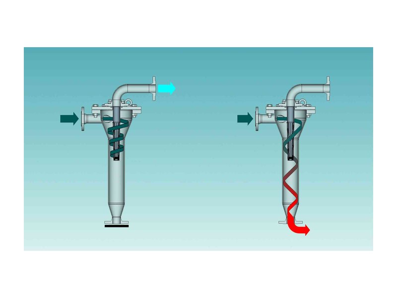
ATF is not a classic back-flushing filter but a hybrid of a centrifugal separator and a filter. It is designed for water and water-like fluids with high and strongly fluctuating contamination — up to several grams of solids per litre. In a single pass, ATF separates particles of different densities, for example sand and plant debris.
Operating principle and design
The fluid enters the housing tangentially and, because of the conical cross-section, moves downwards in a spiral. Centrifugal force presses particles that are denser than the fluid against the wall, and they settle in the lower section. Lighter particles are retained by the conical wedge wire element in the centre — it guarantees the defined filtration rating and keeps contamination from reaching the clean side even when operating conditions change. The collected contamination is discharged periodically through the drain valve: for a few seconds part of the unfiltered flow flushes the element and the housing. Since only part of the flow is used for flushing, filtration continues.
When to choose ATF instead of a conventional filter
- High and variable contamination — for example river or surface water after a flood.
- Many heavy particles such as sand, which make a conventional filter back-flush too often.
- A pre-filtration stage is needed upstream of RF3/RF6 and RF4, sand filters or membranes.
- A replacement for a hydrocyclone without the risk of carry-over when operating conditions change.
Advantages
- Consistent filtrate quality despite fluctuations in pressure and flow rate.
- Continuous filtration with constant self-cleaning.
- No rotating parts — easy to service.
- Several units can be combined into a skid for higher flow rates.
- More compact than plate separators and sand filters.
Applications
Key specifications of ATF
| Connection | G 1" – DN 200 (sizes ATF-1 … ATF-4) |
|---|---|
| Flow rate | up to 400 m³/h per unit; more with a skid of several ATF units |
| Filtration rating | depends on the particle properties and operating conditions; wedge wire elements 200–3,000 µm; heavy particles are separated effectively even below 100 µm |
| Operating pressure | 1–16 bar |
| Temperature | up to 90 °C |
| Pressure drop | relatively low, < 1.0 bar (per the ATF-40 version data sheet) |
| Control | no control, manual, electro-pneumatic or electrical drain valve, with or without timer |
| Particle size | 7.5 g/cm³ (metal) | 2.6 g/cm³ (sand) | 1.7 g/cm³ |
|---|---|---|---|
| > 100 µm | 99 % | 98 % | 77 % |
| 75–100 µm | 92 % | 84 % | 35 % |
| 50–75 µm | 87 % | 78 % | 21 % |
Limitation: the smaller the density difference between particle and fluid, the smaller the contribution of the centrifugal stage. Light particles are retained only by the filter element, so ATF does not replace fine filtration — for that, ATF is installed upstream of RF3/RF6.
How to choose a series
RF3/RF6, RF5 or RF7?
All three use the same technology; the difference is in layout and range. RF3/RF6 is the versatile vertical filter, DN 50–900, filtration from 25 µm. RF5 has a vertical inlet, for large pipelines DN 250–900, coarse filtration from 200 µm, up to 10 bar. RF7 is the horizontal housing for where height is limited.
Low flow rate?
RF4 — up to 385 l/min at pressures from 2 bar. RF12 — up to 80 l/min if the inlet pressure is low, from 0.7 bar, and a brief interruption of supply during back-flushing is acceptable.
Fuel or oil?
RF9 — filtration from 1 µm, up to 180 °C, back-flushing without mixing with air, heating for viscous media. Suitability for a particular medium is confirmed during selection.
Not enough pressure for back-flushing?
RF10 and RF12 with JetFlush technology: back-flushing depends only on the inlet pressure, not on the pressure on the clean side.
Lots of sand, dirty water?
ATF — the centrifugal stage takes most of the load of heavy particles, and the wedge wire element guarantees the filtration rating. For fine filtration — ATF combined with RF3/RF6.
Series comparison
| Series | Main purpose | Distinctive feature | Flow rate, max.* | Rating | Medium |
|---|---|---|---|---|---|
| RF3/RF6 | Universal automatic filtration | Variable flange positions, up to 100 bar depending on version | 7,500 m³/h | 25–3,000 µm | Water, emulsions, low-viscosity fluids |
| RF5 | High flow rates, coarse filtration | Vertical inlet, DN 250–900 | 4,200 m³/h | 200–3,000 µm | Water, coolants |
| RF7 | Installation with limited height | Horizontal housing, pivoting lid | 7,500 m³/h | 25–3,000 µm | Water, emulsions, low-viscosity fluids |
| RF4 | Low flow rates | Rotating element plate, G 1"–G 2" | 385 l/min | 25–1,000 µm | Coolants, water |
| RF9 | Fine filtration of fuels and oils | Hydropneumatic back-flushing, up to 180 °C | 1,000 m³/h | 1–500 µm | HFO, MDO/MGO, biodiesel, lubricating oil, coolants |
| RF10 | Ballast water, low pressure | JetFlush, back-flushing driven by inlet pressure | 3,500 m³/h | 25–3,000 µm | Seawater and ballast water |
| RF12 | Machine tool coolants, low pressure | JetFlush, from 0.7 bar at the inlet | 80 l/min | 25–100 µm | Coolants |
| ATF | High and variable contamination | Centrifugal stage + wedge wire element, no rotating parts | 400 m³/h per unit | By particle properties | Water and water-like fluids |
* Maximum for the series size range. For a specific size, the flow rate depends on the filtration rating, viscosity, contamination and permissible pressure drop.
Automatic back-flushing in operation
See how the filter cleans its filter elements and removes the accumulated contamination without stopping operation.
Video coming soon
16:9 format, no autoplay
Video description
The description and transcript will be added together with the video. Recommended structure: 1) filtration — the fluid flows through the filter elements from the inside to the outside; 2) differential pressure rises as contamination builds up; 3) back-flushing starts; 4) the reverse flow carries the contamination to the back-flush line; 5) return to filtration. The description should name the series shown in the video.
Filter selection and technical advice
The series and size are selected according to the properties of the medium and the contamination. To speed up selection, please prepare:
- the medium and its viscosity (cSt) at operating temperature;
- flow rate: operating and maximum;
- operating pressure and pressure in the back-flush (drain) line;
- medium temperature;
- type of contamination, particle size and concentration (mg/l);
- required filtration rating;
- pipe diameter, installation location and space constraints;
- requirements for materials, power supply and control.
LLP PowerSteel — official HYDAC distributor in Kazakhstan
Send us your parameters via the form on the contacts page or contact us directly.
Request technical advice